Wave-Particle Duality
Waves can exhibit particle-like characteristics and particles can exhibit wave-like characteristics. Is it possible that waves alone could behave as particles? What if the universe is composed of a single medium capable of supporting vibrations? And if all that we perceive as matter and energy is only vibrations (electromagnetic waves) within this medium? This is all there is and nothing else.
Years ago the ether was proposed as a medium to support the movement of electromagnetic waves through empty space. After all you can not have water waves if you have no water to support the waves. You can not have sound waves without air or some other medium to support the wave.
One major objection to the idea of the ether is that it would cause resistance to the movement of matter through the medium. That objection disappears if matter itself is only a vibration in the medium. Thus, without the medium there is no light, there is no matter. It might be this medium is solid. It certainly must have a high rigidity to transport light waves at such a high velocity.
With this in mind, we can use imagination, to suggest possible explanations for some observed physical phenomenon. How could the combinations of various electromagnetic waves or impulses ever behave as a particle? Let us compare attributes of particles with those of waves.
Attributes of particles
A particle has mass, it is localized in space. Two or more particles cannot occupy the same space at the same time. A particle can have any relative velocity from 0 to almost c (the speed of light).
Attributes of waves
An electromagnetic (EM) wave has no mass. It is not localized; it spreads out over a large volume of space. Many waves can occupy the same space at the same time. These waves have only one relative velocity c. They have attributes of wavelength, frequency, intensity and amplitude of the disturbance (electric charge).
First let us consider photons.
How photons could be defined in terms of electromagnetic waves
The photoelectric effect is the emission of electrons from a body (usually metal) when exposed to electromagnetic waves. The higher the frequency of the wave, the more energy the ejected electrons have. A bright light yields more photoelectrons than a dim one of the same frequency, but the electron energies remain the same. That is the greater the frequency of the wave the greater the speed of the ejected electrons. At frequencies below a certain critical frequency fO, no electrons are emitted. The critical frequency fO, is characteristic of each particular metal.
There is no detectible time interval between the arrival of light at a metal surface and the emission of photoelectrons. Since the energy in an EM wave is supposed to be spread across the wave front, a period of time should elapse before an individual electron accumulates enough energy (several eV) to leave the metal.
To explain this, in 1905 Einstein realized that the energy in light is not spread out over the wave front but is concentrated in small packets, or photons. Einstein described the photoelectric effect with the equation,
hf = KEmax + f. The energy of the photon is planks constant (h) times its frequency (f) equals the maximum kinetic energy (KEmax) of the ejected electron plus the minimum energy (f) needed for an electron to leave the metal (the metal’s work function f )
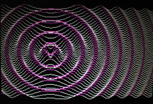
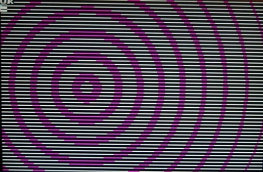
The total energy of the electromagnetic wave depends on the amplitude of the wave as well as its frequency. In fig. 1a we see a computer representation of an electromagnetic wave radiating from a single point on the x,y plane viewed at a 45O angle. Here the height of the wave is above a minimum value is colored purple. We can see as the wave expands the amplitude of the wave (and its resultant energy) is reduced. But this energy is evenly distributed in all directions. Fig. 1b is the same but viewed straight on from above the plane. These drawings were created in GWBASIC with a computer program called 3DWAVE-1.
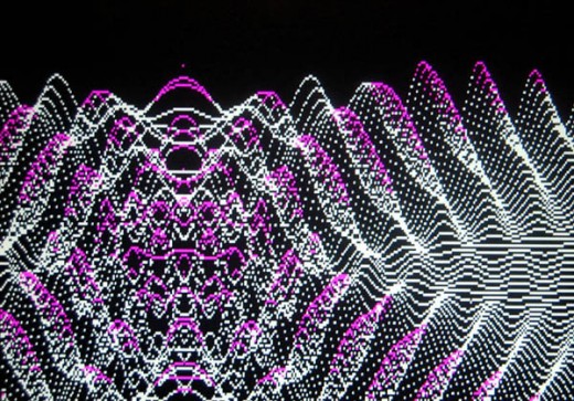
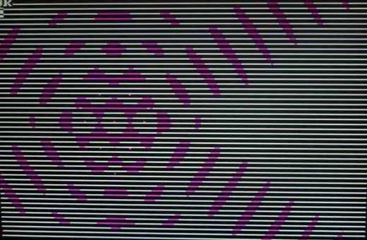
When light radiates from a light bulb or the sun, it does not radiate from a single point but from many different points within the radiating body. As the waves from these different points pass through each other they create both positive and negative interference in the wave’s amplitude. In fig. 2a and particularly fig. 2b we see how radiation from only nine different points, indicated by nine white points, creates interference. This radiation interference breaks the continuous waterfronts into little bundles of energy. Any source bright enough to be seen would be radiating light from a great many more then nine atoms at a time. These drawings were created in GWBASIC with a computer program called 3DWAVE-9
Photons are areas where many different spherical impulses of the same wavelength intersect and are in phase at those areas. In these illustrations we are seeing only the wave in the x,y plane. A complete photon would consist of a limited wave train, containing an equal number of positive and negative impulses. The positive and negative impulses are of equal strength and this prevents the photon from carrying a charge. The energy of the photon would equal the energy of all the waves it is composed of. If a photon were the result of a combination of one million waves, the photon would have energy equal to one million times that of the energy of a single wave plus the energy of the waves canceled elsewhere.
How electromagnetic waves might behave as particles of matter
The magnetic fields of an electromagnetic wave are created by the varying electric fields of that same wave. Thus to understand how electromagnetic waves might behave as a particle we only need to study the waves varying electric fields. If a strong charge (an impulse) should occur in space it will expand as a hollow sphere of charge. After the impulse has passed, the space will oscillate between positive and negative charge. These oscillations will dampen out shortly after the impulse has passed. As the sphere of charge continue to expands, the amount of charge (q) the wave front is able to impart to an area of space it is passing thought is reduced by the amount distance the sphere surface is from the origin.

In panel 1 of fig.3 we see an arrow at point A, representing an impulse of an electric field with a magnitude of +e, the elemental charge.
In panel 2 the arrows AR and AL represent the magnitude of the electric field of the wave front of the expanding spherical wave. The ellipse at the top represents the circumference of the expanding spherical wave. The electric field at point A is oscillating and is now at zero magnitude.
In panel 3 the electric field at point A has oscillated to its most negative magnitude.
In panel 4 the electric field at point A has oscillated back to zero magnitude.
In panel 5 the electric field at point A has oscillated to its most positive magnitude. However, because of the damping of the oscillation, the magnitude of this second positive peak (the first complete cycle) is much smaller than +e. The wave front will continue to expand through space for a long time.
As time passes all existing electromagnetic impulses are reduced in amplitude. On the left of fig. 3a, we see how the oscillations of the electric fields at a single point dampen out in time. On the right we see, since the wave is expanding into space, as the wave moves out from its origin the amplitude or energy of the wave front is reduced by charge divided by distance from origin q/r2.
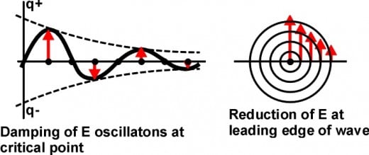
This is analogous to a drop of water falling into a pond of still water. The impulse, caused by the drop hitting the water, spreads out as an ever increasing circle. After the impulse has passed through an area of water, the surface will oscillate, and these oscillations will die out leaving still water again.
Many impulses or waves can pass through the same volume of space at the same time. These disturbances in space can pass through each other, and after doing so continue on unaffected by the encounter. However, as they pass through each other, due to the principle of superposition, the total amount of charge is the algebraic sum of all the charges in that space at that time.
The interaction of waves with waves
When electromagnetic waves pass through each their amplitudes (charges) are added together.
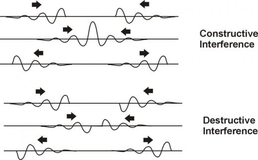
At the top half of fig 4 we see two positive impulses and their accompanying oscillations approaching each other. When the two peak charges coincide, the resultant peak charge is equal to the sum of the peak charges of the individual impulses. This is constructive interference. Where a peak and a trough coincide in the lower half of fig. 4, they cancel each other and no charge occurs. This is destructive interference.
If one hundred peak charges occupied the same space the resultant charge would be the algebraic sum of the one hundred peaks. The same is true for a thousand wave peaks or a million wave peaks. Is there no limit? This line of reasoning leads us to the KEY CONCEPT of this article. THERE MUST BE A LIMIT TO THE AMOUNT OF CHARGE AT A POINT WITH WHICH NO MORECHARGECANPASS THAT POINT.
Let us assumed that there is a maximum charge or critical amplitude, in which a charge that cannot be exceeded. This charge could be the elementary charge e which equals + or -1.6021892 x 10⁻¹⁰ coul. If the addition of the charge amplitudes of waves occupying the same space equals or exceeds this maximum limit, then the impulses cannot pass this point. All of the waves will be reflected from this maximum peak point in space. This maximum peak charge becomes the origin of a new impulse, radiating in all directions away from that critical point. If the critical point is positive, the wave radiating away from the point will be more positive than negative. If the critical point is negative, the wave radiating away from the point will be more negative than positive. This would explain why most particles carry the elemental charge of + or -e.
A wavical shown as energy trapped between two critical peaks
Every particle (or wavical) has an electromagnetic wavelength associated with it. That is it’s Compton wavelength l = h/mOc (planck’s constant divided by the rest mass of particle times the speed of light). To study this, examine fig 5. These drawings with fig 5A illustrate how two maximum peak charges could trap wave energy between them, creating a wavical that behaves as a particle.

In panel 1 of fig. 5 the time is set to 0 in both the wavical system and the observer’s system. The gray dotted line circle represents the area of the wavical. In this area we see two critical points of a wavical A & B. These two points are one half Compton wavelength (l) apart. The red arrow at point B is in the negative oscillation of the electric field and is much less than –e. This is because the electric field at B peaked at +e, one half time period ago. The red arrow at point A indicates that the electrical field is at the maximum positive peak of +e at that point. Thus no waves can pass through this point. All the waves arriving at this point at this instant are reflected away from this point. This creates a new spherical electromagnetic wave emanating from point A.
In panel 2 this wave is shown as a shaded sphere. The blue line around the shaded sphere represents the leading edge of this wave. The leading edge of this wave has reached point B after ½ time period. The red arrow at the left side of the sphere represents the magnitude of electric field at every point on the surface of this spherical leading edge. The small red arrow at point B represents the magnitude of the first complete oscillation of the electric field at point B. The magnitude of this electric field combines with the electric field of the leading edge of the wave from point A to equal a magnitude of +e. Thus no electromagnetic waves can pass through point B. This creates a new spherical electromagnetic wave emanating from point B. The leading edge of this wave is positive and radiates through space as a positive electric charge.
In panel 3, time is at one time period in both time systems. The leading edge of this wave has reached point A after ½ time period. The magnitude of this electromagnetic field at point A combines with the electric field of the leading edge of the wave from B to equal a magnitude of +e. Thus a wave is continual reflected back and forth between these two points. This produces a continuous spherical waves of charge radiating away from the wavical
How the charge at the wave front from one critical point, can combine with the charge of the peak oscillation at the other critical point to produce the element
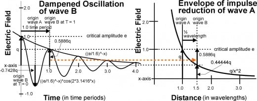
Fig. 5A shows how the addition of the second peak oscillation at the origin of wave B when added to the wave front of wave from point A creates a new critical amplitude. This starts a new wave with its origin at point B. When this new wave front reaches the oscillation at point A, they add together to produce a new critical amplitude of +e at point A.
A wavical shown as energy trapped between two moving critical peaks
When an observer sees a wavical moving through space waves radiating from the wavical are affected by the Doppler effect. This causes its Compton wavelength to be shortened and its time is dilated. It is the Doppler effect that creates the effects of relativity. With a velocity of 0.6c it takes 1.25 times longer for the cycle of the Compton frequency to repeat itself than when the wavical is not moving through space.
When the oscillation at one point adds with the wave front from the other point and they create an amplitude much greater than the e. This extra energy becomes the velocity for the wavical. This is illustrated in fig 6A and fig 6B.

In panel 1 of fig. 6A, time is set at 0 in both the wavical and the observer’s time systems. The area of the wavical is indicated by the ellipse outlined in a dotted gray line. We see two critical points A and B of a wavical. These two points are one half Compton wavelenght (l) apart. However, since the wavical is moving at 0.6c, the distance between them is reduced to 0.8 the original distance between them to 0.5l * 0.8 = 0.4l. The red arrow at point B is in the negative oscillation of the electric field and is not as negative as –e. The red arrow at point A indicates that the electrical field is at the maximum positive peak greater than +e by 1.25 times, at that point. It is the magnitude of charge over e that gives the wavical its velocity of 0.6c. This is illustrated by rotating the arrow qp by 30.96O so the top is at +e. This is the same angle as the time axis in the Minkowski diagram. The magnitude of the charge creates a new spherical electromagnetic wave emanating from point A.
In panel 2 this spherical wave is shown as a shaded gray circle. The leading edge (the blue line circumference) of this wave has reached point B. To calculate the time it takes for the wave to travel from point A to catch up to the moving point B is t2 in the observer’s time system. Ct2 is the radius of the spherical wave at the time t2. T1 is the time it would take for the wave to move from A to B if these points were not moving.
ct2 = ct1 +vt2 or t2 = ct1/(c-v) where ct1 = 0.5l (1-(v/c)2)1/2 = 0.4l v/c = 0.6
thus
t2 = t1/(1-v/c) = 0.4/(1.0-0.6) = 1.0 time period
However, since the wave front has just now reached point B, the time at B is 0.5 in wavical time units. During this time the two critical points A&B have moved the distance of d = vt2 = 0.6x1.0l = 0.6l. The blue line represents the leading edge of this wave. The red arrow at the left side of the sphere represents the magnitude of electric field at every point on the surface of this spherical leading edge. The small red arrow qp at point B represents the magnitude of the oscillating electromagnetic field at point B. The magnitude of this electromagnetic field combines with the electromagnetic field of the leading edge qe of the wave from point A to equal to a magnitude 1.25 times greater than +e. This creates a new spherical electromagnetic wave emanating from point B.
To = observer’s time in Compton periods.
Tb = wavical’s time in Compton periods.
Ta = time at point A = Tb+(1/2)v/c

In panel 3 of fig.6B the leading edge of this wave from B has reached point A. The magnitude of this electromagnetic field qe combines with the electromagnetic field qp of at B is greater then +e. The time it takes for the wave to travel from point B to point A is t3 in the observer’s time units. Ct3 is the radius of the spherical wave at the time t3 is the time in the observer’s time system. T1, is time it would take for the wave to move from A to B if these points were not moving.
ct3 = ct1 – vt3 or t3 = ct1/(c-v) where ct1 = 0.5l (1-(v/c)2)1/2 = 04l v/c 0.6
thus t3 = t1/(1+v/c) = 0.4/(1.0+0.6) = 0.25
Since the wave front has just reached point A the time at point A is 1.0 time period in the observer’s time units. During this time the two critical points A&B have moved the distance of d = vt2 = 0.6x0.25 = 0.15l.
The blue line represents the leading edge of this wave. The red arrow at the left side of the sphere represents the magnitude of electric field qe at every point on the surface of this spherical leading edge. The small red arrow at point A represents the magnitude of the oscillating electromagnetic field qp at point A. The magnitude of this electromagnetic field combines with the electromagnetic field of the leading edge of the wave from A to equal to an electrical field of a magnitude 1.25 times greater than +e. This creates a new spherical electromagnetic wave emanating from point B.
In panel 4 the leading edge of this wave has reached point B. The magnitude of this electromagnetic field qp at point B, combines with the electromagnetic field qe of the leading edge of the wave from B is 1.25 times greater then +e.
Thus a wave is continual reflected back and forth between these two points. The time for the wave front to move from point A to point B is 1.0 of the observer’s time units. For the wave front to move from A to B takes 0.5 of the wavical’s time units.
Why does it take 4 times longer for the wave front to travel from A to B than from B to A in the observer’s time and the same amount of time both ways in the wa
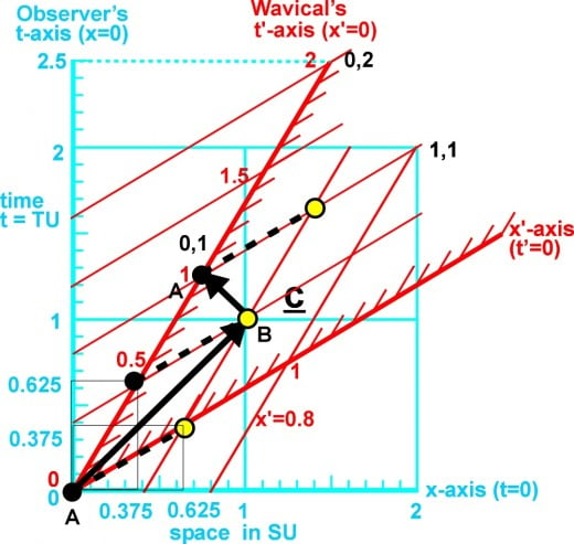
This is because time at point A is not synchronized with time at point B. The time at the trailing point is ahead of the time at leading point, by the distance d between the two points times their velocity d(v/c) = 0.5(0.6c) = 0.3 time units. In fig. 6a & 6b, Ta = time at point A and Tb = time at point B. This can be illustrated using a Minkowski diagram fig. 7. On the observer’s time axis we see the light travels (heavy black arrow) from A to B in one time unit. From B back to A in 0.25 time units, for a total round trip of 1.25 time units. On the wavical’s time axis we see the light travels (heavy black arrow) from A to B in 0.5 time units. From B back to A in 0.5 time units, for a total round trip of 1.00 time units.
The definition of a wavical
The definition of a wavical is the electric energy trapped between two or more reoccurring critical electric peaks (reflection points) and this energy behaves as a particle. Thus we have a localized vibration in space. Mass is the measure of this trapped energy. The wavelength of a wavical at rest is the Compton wavelength for the particle lO = h/mOc. The frequency of a static wavical is fO = c/lO = mOc2/h. Its period is the reciprocal of the frequency is TO = h/ mOc2. When the wavical is moving relative to the observer the wavical its period is slowed by relativity to T = gh/mOc, where g = 1/(1-(v/c)2)1/2. The energy that radiates away from the critical peaks into space is a contentious wave of electrical charge. These are certainly attributes of a particle. The critical positive charge is +e thus, the charge on a proton is +e. The critical negative charge is -e therefore, the charge on an electron is –e, even though the wavelength of the electron is over 1,835 greater than the wavelength of the proton.
With this arrangement the wavical is stable as long as its wavelength is in the proper range. The proton is certainly the most stable wavical, having a rest wavelength of 1.32 x 10⁻¹⁵. Hence space must have a resonance frequency of 2.27x10²³ Hz for the proton and a secondary resonance frequency of 1.25x10²⁰ Hz for the electron. The frequency for the neutron is very close to that of a proton and this is why the neutron is able to exist so long alone before decays into a proton, electron and neutrino.
All wavicals are affected by the waves emanating from other wavicals. With so many wave fronts passing through space, occasionally enough wave fronts will pass through the same point in space at the same time to create a new critical charge. When this happens a new wave front will radiate away from this point. If there is no other reflective point there will be no continuous wave. Or if were another reflection point and it is not strong enough to sustain continous reflections. This will appear as if a new particle has appeared from nowhere and then disappeared, a virtual particle.
The Electric Charge
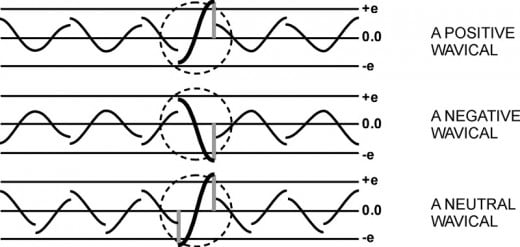
The charge of a wavical depends on the impulse that is being reflected back and forth within the wavical. If the impulse is positive then the waves emanating from the wavical will have a positive charge. That is the positive part of the wave is greater than the negative part of the wave. If this impulse were negative then the radiating waves will carry a negative charge. If the wavical contains two impulses, one positive and one negative, then the waves from the wavical are neutral. See figure 8
Wavicals with like charges repel each other
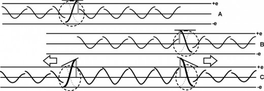
The waves that radiate from a wavical affect the space around it. If two positive wavicals were close to each other, the amplitude of the wave radiated from one wavical will increase the amplitude of the closest peak point in the other wavical and vice versa. The change in amplitude at a peak point in a wavical will cause a change in its wavelength and its velocity. Since the amplitude at peak point closest to the other wavical has increased, the velocity increase will be directed away from the other wavical. The same is true for two negative wavicals. Thus wavicals of like charge repel each other by causing an unbalanced force between them.
Wavicals with unlike charges attract each other
In figure 9 we see the energy of waves between the two positive wavicals is greater than the energy of the waves outside the two wavicals. Thus the greater energy between the two wavicals shoves the wavicals apart.
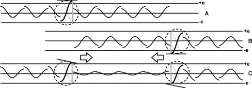
Since both of these wavicals have the same wavelength, when they get close enough together so that their external impulses are large enough to reduce the amplitude of the internal impulses of wavical below the critical charge, then that peak point ceases to exist. Hence, the wave energy cannot be reflected back. It simply dissipates into space, causing both wavicals and their accompanying masses to disappear in a release of energy. These two wavicals could have been an electron and a positron obeying the laws of antimatter.
The Electron and the Proton
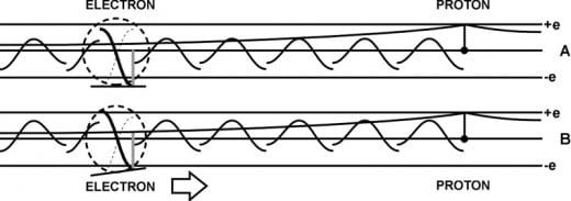
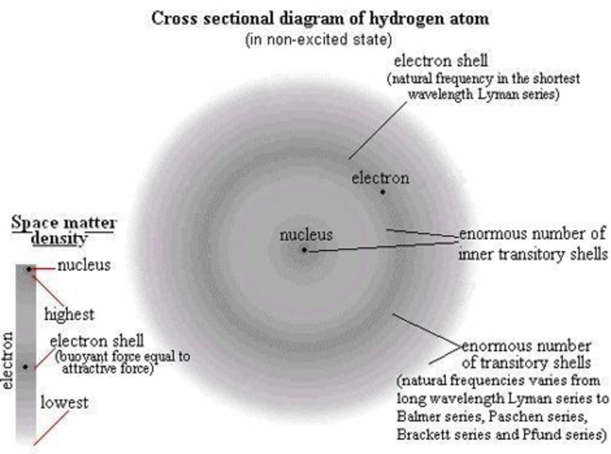
In figure 11 we see an electron and a proton. Since the proton's frequency is over 1800 times greater than the electron, the electron cannot sense or react to the proton's individual positive and negative peaks. The electron will only sense the average of the proton's oscillating peaks as a positive field that increases the closer the electron gets to the proton. This positive field causes a reduction of the negative charge in the electron's peak point nearest the proton. But not to where it would drop below the critical charge. This reduces the pressure on that side of the electron causing it to move toward the proton. The electron waves will follow the proton's average positive envelope as the line of equilibrium. This means as the electron approaches the proton its negative peaks are reduced and its much smaller positive peak is increased. At a certain point the positive peak of the electron will have increased to the critical charge. Then it becomes a positive peak point that peaks positive at the same instant that the other peak point is peaking negative. Here the electron is neutral. It is equally as positive as it is negative. At this distance from the proton, the electron and the proton form a stable hydrogen atom. If the electron tries to move closer to the proton its positive peak becomes larger, repelling the electron from the proton. If the electron tries to move away from the proton, its negative peak increases causing it to be pulled back toward the proton. However, a just captured electron has too much energy to form a stable hydrogen atom. The electron must radiate away some of this excess energy as electromagnetic waves. The rest of the excess energy appears as the velocity used orbiting the proton.
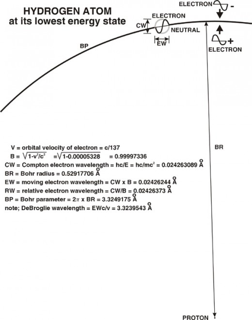
In fig. 12 we see the electron orbiting the proton with a velocity of about 1/137 of c, at a distance of about ½ angstrom. At this distance the positive charge from the proton nullifies the negative charge of the electron to produce a neutrally charged electron. This is the Bohr radius of the stable orbit of the electron in the hydrogen atom. If the electron should receive a certain amount of energy from electromagnetic waves, the electrons velocity will change and the electron will move to a larger orbit. At the larger orbit the electron will become negatively charged and be attracted toward the proton. The electron can only return to its stable orbit by emitting this additional energy as electromagnetic waves or impulses.
The Nuclear Force
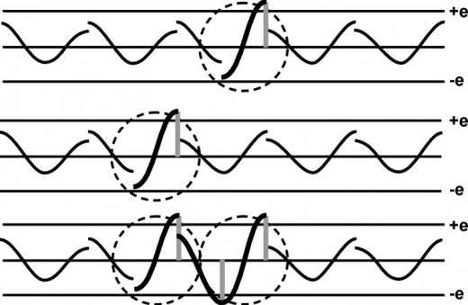
Two protons (hydrogen nuclei) normally repel each other. However, in fig. 13, if they are forced together by high velocity, they can combine to form one wavical. This wavical will have 2 positive peaks and one negative peak (a proton-neutron pair, a deuterium nucleus). This is called the proton-proton cycle. The addition of their maximum negative charge, meets or exceeds the critical negative charge, producing a negative impulse. The two protons form a stationary wave which will produce two positive impulses and one negative impulse every ½ period. The two positive peaks are one wavelength apart. The negative peak is ½ wavelength from both positive peaks.
When the protons first meet, the positive velocity peaks far exceed the limit. This excess energy is radiated away as a positron e+ and neutrino n. These are two other wavicals of different wavelengths, created from the excess energy. These are not shown in fig. 13. The wavelength of the positron is over 1800 times the wavelength of the proton. Thus the proton would go through more than 1800 cycles to release a positron.
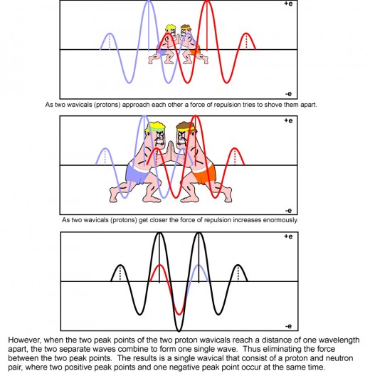
Two of these proton-neutron wavicals can be combined into a single wavical the alpha particle. A very stable wavical since the four positive peak points occur at the vertices of a tetrahedron, each positive peak point one wavelength apart. All the waves reinforce each other.
The nucleus of every atom may be a single wavical where the impulse from each peak point tends to reinforce the other peak points. An atomic nucleus has a critical positive peak for every proton and neutron in it and a critical negative peak for every neutron in it. As the nucleus increases in size, it is impossible for each peak point to be an integral number of wavelengths apart from all the other peak points even with the shifting of peak positions within the wavical. This will cause an interference in the wavical pattern which causes some large nuclei to be unstable. This prevents the formation of nuclei beyond a certain size. This interference is the basis for the weak force.
The reason that the nuclear force range is so short is that a positive peak point in one proton must be ½ wavelength from the negative peak point in the other proton. If for any reason the protons are moved apart, they no longer form a continuous wave and the particles repel each other. This is the reason that the nuclear force falls off so fast. The nuclear force, rather than being an energy radiated into space, is more a condition of position. One proton must have one of its positive peak points one wavelength from the other proton's positive peak points. This way they tend to support each other's position, rather than repel each other.
The particle attributes of a wavical
1. A wavical is localized in space, electromagnetic waves trapped between two critical peak points that reflect the wave back and forth. These two critical peak points are separated in length by 1/2 the wavical's wavelength and in time by 1/2 the period of one of the wavical’s cycles.
2. Two or more wavicals cannot occupy the same space at the same time. Even though two or more wavicals can join together, sharing a critical peak point, they still occupy separate spaces of at least 1/2 wavelength.
3. A wavical can have any speed from 0 to almost c (the speed of light) and cannot exceed the speed of light. If a wavical were to move in any direction through 3-dimentional space with the speed of light, the signal from one critical peak could never reach the other critical peak to complete one cycle. Thus time would stand still for that wavical.
4. The energy that radiates away from the critical peaks is a continuous wave of electrical charge. This charge can be positive (positive peaks greater than negative peaks), negative (negative peaks greater than positive peaks), or neutral (positive and negative peaks equal).
The Pauli exclusion principle
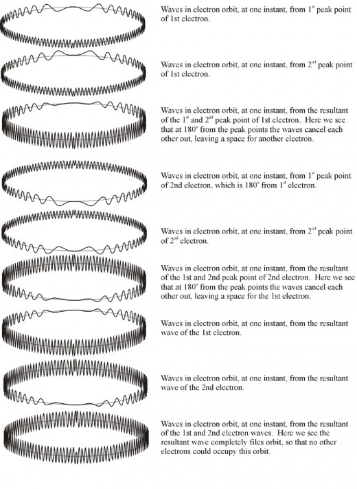
The Pauli Exclusion Principle: No two electrons in an atom may occupy the same quantum state. That is, no two electrons in an atom may have the same four quantum numbers. From this it is concluded that only two electrons can occupy the same orbit around the nucleus of an atom. The physical reason for this can be seen by examining the waves emanating from the two peak points of an electron in orbit around a nucleus. These two waves cancel each other on the other side of the orbit. Since there are no waves from the first electron at this point allows another electron to occupy this position on the same orbit.
The top drawing in fig. 15 shows the calculated amplitude of the wave from the first critical point of the 1st electron at each point on the electrons orbit. The second drawing in fig. 15 shows the calculated amplitude of the wave from the second critical point of the 1st electron at each point on the electrons orbit. The third drawing in fig. 15 shows the amplitudes of the first two drawings are added together showing that the amplitudes cancel on the opposite side of the orbit from the electron. Thus leaving a space that can be occupied by another electron. The next 3 drawings show the wave amplitudes from another electron 180O from the first electron. The last 3 drawings show the wave amplitudes of both electrons added together. The two negative charges of the electrons are balanced by two positive charges in the nucleus. This is studied in the computer program eleorbit.
Gravity
Gravity may be similar to the Casimir effect. The Casimir effect occurs with two parallel metal plates. Electromagnetic radiation of any wavelength can strike the parallel metal plates from the outside, but radiation trapped between the plates can only have certain wavelengths (harmonics). The resulting imbalance produces inward forces on the plates. Only a limited number of radiations are allowed to occur within a molecule, fewer inside an atom, still fewer inside a particle such as a proton, neutron or electron. Thus effect of gravity on a body may result from all the radiation the body receives from the entire universe.
When most electromagnetic impulses and wave trains bombard atoms, the atoms tend to move in the same direction as the waves are moving. This tendency is caused when a proton in the atom reaches a peak point at the same instant that a positive peak of the wave is moving through that point. Hence, waves could pass thought an atom with no effect on it until one of the peak points of the atom and a peak on the wave coincide. This can cause free atoms to jump about in different directions when effected by different waves traveling in different directions. When a larger body of matter is bombarded from all different directions by waves, the multiple little pushes all tend to be directed toward the center of the body of matter.
If two bodies of matter are close to each other in empty space, each body will shield the other body from some of the energy of the waves that would have hit it as shown fig. 16. Thus there is less bombardment on the side of each body that is closest to the other body of matter. The inequality in bombardment causes the two bodies to move toward each other. This shielding effect is symbolically illustrated in fig. 16. The closer the bodies are to each other the greater the shielding effect. The more massive the bodies are the greater the shielding effect. The denser the bodies are the greater the shielding effect. It is this shielding effect that causes what we call a gravitational field around a body of matter.
However, the planets of the solar system must receive more radiation from the sun than from outer space. Much of the radiation from the sun has a shorter wavelength than the radiation from outer space. Some of the shorter radiation from the sun can be absorbed by matter. When matter absorbs radiation it moves toward the source of the radiation. As opposed to when matter reflects radiation it moves away from the source.
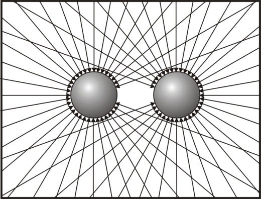
Gravity is analogous to drinking a liquid through a straw. Sucking on the straw does not attract the liquid into the mouth. But by lowering the air pressure in the mouth, the greater air pressure on the surface of the liquid, in the glass, forces the liquid through the straw into the mouth. Matter does not attract other matter, instead radiation outside of the particles of matter shoves the them together.
The Universe
Does the universe have limits to its extent? And if it does what lies beyond those limits? If our universe consisted of some medium that is capable of supporting waves, then it might be bounded. It would have some shape, perhaps a sphere. Whatever its shape it might be floating in an endless sea of nothingness. There may even be other bodies similar to our universe out there that we could never know about, since no signal, no wave, no particle could travel through the void that separates them from our universe. Possibly all the waves, hence everything that exist in our universe today might be the results of a collision between our universe and another, billions of years ago (the big bang). That collision would have created waves that are still traveling through our universe today. Since there is nothing to vibrate beyond the surface of our universe, no energy is radiated away, so that the energy in our universe would remain constant. Any wave or particle in our universe coming to the boundary between the medium of space and the void of nothingness will be reflected back into our universe. By looking for arrangements that appear as mirror images of other galaxy arrangements that are close to them, one might locate some of the limits of the universe.
If our universe a giant ball of ether, a super solid, what is it composed of? Perhaps it is composed of particles with a diameter of planck’s constant. This could account for why this constant appears in so many equations. But what could hold these particles together? It could not be any force that reaches through absolute empty space. Perhaps the particles have a sticky surface and simply stick together.
In order to draw transversal waves of a one dimensional object like a string, requires two dimensions. In order to draw transversal waves of a two dimensional object like the surface of water, requires three dimensions. It stands to reason that in order to draw a transversal wave of a three dimensional object like an electromagnetic wave, requires four dimensions. Thus our universe may consist of four spatial dimensions. But if everything in the universe has a forth spatial dimension, why can not we see it. Perhaps, movement through the ether causes the relativity effects. Maybe every thing in the universe is constantly moving through space with the speed of light. Then lengths in the direction of that movement would be reduced to zero. This would leave only 3 dimensions visible. The direction of this movement for each object could be called its time axis. The movement between objects is due to the angle between the object’s time axis. This would match the Minkowski diagram.
Quarks
I am not sure if quarks even exist. If they do exist, they are not complete particles. They would also have to be composed of reflected waves. They cannot exist alone. but, only by sharing their sub-peak-points with those of other quarks.
. In particles like Hadrons. when the wave front from the opposite peak combines with the first oscillation peak the combined charges do not equal the elementary charge. In order to produce the elementary charge 2 or 3 wave fronts must arrive at the first oscillation peak.
This is illustrated for meson which composed of two quarks in figures 17 through 21.
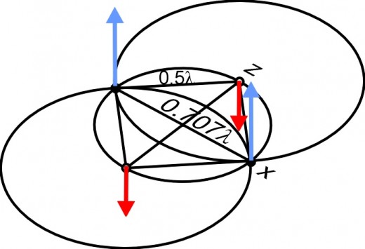
In Fig. 17 we see 2 blue arrows on the x axis, representing 2 peak points of the elementary electric charge e. The red arrows on the z axis, represents electric oscillation at the points where peak points occurred one half period ago. We see these arrows the oscillation is at its most negative value.
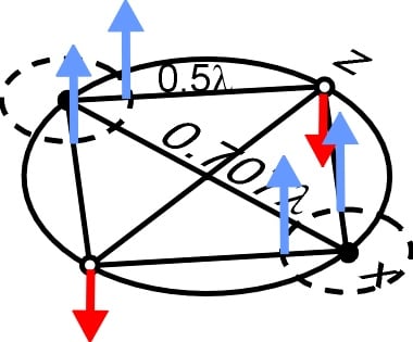
In Fig. 18 the blue arrows represent the charge of the circular wave fronts moving from the peak points in fig. 17. The height of these arrows represents the electric charge by e/r2, where r is the radius of the circular wave front. The red arrows indicate the charge of the oscillations are approaching zero.
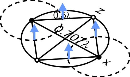
In Fig. 19 the blue arrows represent the reduced charge of the circular wave fronts moving from the peak points in fig. 17. The oscillations (red arrows) of the charge at the points on the z axis has reached zero.
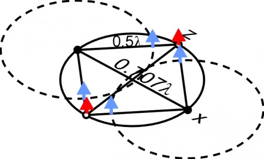
In Fig. 20 the blue arrows represent the reduced charge of the circular wave fronts moving from the peak points in fig. 17. The oscillations of the charge at the points (red arrows) on the z axis are now positive.
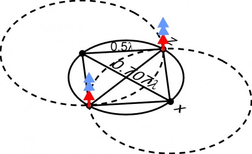
In Fig. 21 the blue arrows represent the reduced charge of the circular wave fronts have now reached the points on the z axis. The oscillations of the charge (red arrows) at the points on the z axis have reached their first maximum amplitude. The sum of these three vectors, equal the critical amplitude +e thus creating the origin of a new impulse at both points.
Hadrons that are composed of 3 quarks are Baryons. Both protons and neutrons are baryons.
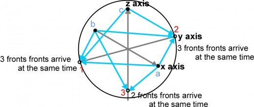
Fig. 22 is a baryon in three dimentions. The three black circles represent peak points (elementary charges) that occur at the same time. The blue arrows represent wave fronts starting from the three black peak points at the same time. The three empty circles represent oscillations from where peak points occurred ½ period before black circle peak points occurred. All three wave fronts arrive at two of the empty circles at the same time. At one of the empty circles only two wave fronts arrive at the same time. The oscillations at each empty circle have peaked by this time. The combination the charge of the peaked oscillation and the charges of the wave fronts produce new peak points (elementary charges) at each of the empty circles. Where the oscillation and only two wave fronts combine they still produce an elementary charge, but with much less force than where the oscillation and three wave fronts combine. These new elementary charges produce new wave fronts that continue the cycle. When the three peak points occur at the same time they appear as three quarks in the baryon. At ½ period latter the three new peak points appear as the same 3 quarks that have rotated 90 degrees.

However, I can find no way to explain fractional charges. Perhaps the higher frequency of the hadrons causes a critical point (a reflection) to occur at a fractional charge.
Summary
In this article we have seen how electromagnetic waves from these different points in a light source pass through each other creating both positive and negative interference in the wave’s amplitude. This interference creates discrete wave packets of energy. These packets of energy are photons. The amplitude (charge) of the waves in these packets is much greater than a single wave front. Thus they act like particles and are able to knock electrons off the surface of metal.
Many electromagnetic waves can pass through the same volume of space at the same time. These disturbances in space can pass through each other, and after doing so continue on unaffected by the encounter. As they pass through each other, due to the principle of superposition, the total amount of charge is the algebraic sum of all the charges in that space at that time. If the total sum of the electric charge equals the elementary charge e which equals 1.6021892 x 10⁻¹⁰ coul, then no electromagnetic waves can pass through this point. All of the waves will be reflected from this maximum peak point in space. This maximum peak charge becomes the origin of a new electromagnetic wave, radiating in all directions away from that point.
If we have two maximum charges that occur 1/2 wavelength apart and peak 1/2 period apart they will trap the waves between them. When the wavelength of the electromagnetic is the right length, then these charges are self sustaining. When the wave front from wave A has traveled ½ wavelength from its origin, it reaches the point where the wave B had started one period ago. At this point the oscillation from wave B is at its peak. The addition of the charge of A’s wave front and the charge of B’s oscillation equals the maximum charge e. This maximum peak charge becomes the origin of a new electromagnetic wave B, radiating in all directions away from that point. In turn when the wave front from wave B has traveled ½ wave length it reaches the point where the wave A had started one period ago. At this point the oscillation from wave A is at its peak. The addition of the charge of B’s wave front and the charge of A’s oscillation equals the maximum charge e. This maximum peak charge becomes the origin of a new electromagnetic wave A, radiating in all directions away from that point. Thus, a new electromagnet wave is created every ½ period and ½ wave length apart. Thus, the wavical is electromagnetic waves reflecting back and forth between critical points. This energy is localized as a particle.
The waves emanating from the wavical transport an electric charge through space. These waves of charge affect other wavicals. Two positive charged wavicals repel each other. A positive wavical and a negative wavical will attract each other. If they are the same size they will come together and their critical peaks will cancel each other releasing all the waves. Since two wavicals are the same size (have the same wavelength) but opposite charge one wavical is matter while the other is antimatter and they annihilate each other. Two proton wavicals will repel each other, unless they are close enough to form a single wave group with two positive critical peaks and one negative critical peak (a proton-neutron pair, a deuterium nucleus). This is an explanation for the nuclear force. It is a matter of position rather than attraction.
We have seen a possible explanation of the Pauli exclusion principle. A suggestion of how gravity may be the result of bodies of matter shielding each other from external radiation. Our universe may be a ball of ether floating in a sea of nothing. The big bang may be the result of our universe, a big ball of ether colliding with another big ball of ether. The resulting waves from this collision created all the matter in the universe that we see today.
These have been a few ideas from outside the box. Some of these ideas may be useful others may not. Some of these may offer plausible explanations for some unexplained phenomenon.
The computer program 3DWAVE_9 illustrates the wave radiation from nine points
Einstein though that the photoelectric effect could be under stood if the energy in the light is not spread out over wavefronts but is concentrated in small packets, or photons. When light radiates from a light bulb or the sun, it does not radiate from a single point, as in fig 1a and fig. 1b at the beginning of this article. The light radiates from many different points within the radiating body. As the waves from these different points pass through each other they create both positive and negative interference in the wave’s amplitude. In fig. 2a and fig. 2b at the beginning of this article, we see how radiation from only nine different points break the continuous waterfronts into little bundles of energy. Any source bright enough to be seen would be radiating light from a great many more then atoms at a time.
To view this radiation from different viewpoints this program must be rendered in three diamensions. To do this we will use analectic geomentry. In analectic geometry there are two combined equations used for rotating all the points in an object by the angle q, on the x,y plane. These equations are
x’ = x*cos q – y*sin q and y’ = x*sin q +y*cos q.By expanding these two equations into 6 equations produces a 2D representation of a 3D object. By using 3 different angles of rotation this representation of a
3- dimensional object can be viewed from any angle. These are seen in lines 640 to 700 of the program.
All of these programs are written in GW Basic
The computer program 3DWAVE-9
100 CLS: REM 3dwave-9 here waves radiate from 9 points
110 SCREEN 1,0: KEY OFF: COLOR 0,1
120 PI=3.14159
130 INPUT "ROTATION ABOUT X AXIS IN DEGREES"; A3
140 CLS
150 A1 = A1/57.29577951:REM converts degrees to radians about the z-axis
160 A2 = A2/57.29577951:REM converts degrees to radians about the y-axis
170 A3 = A3/57.29577951:REM converts degrees to radians about the x-axis
180 D=.5: REM scale of wavelength
190 WL = D*5O:REM wavelength
200 T=300:REM time
210 P=100:REM adjustment to x position
220 YK1=( ( WL^2-( WL/2 )^2)^. 5 ):REM the y distance between rows of points of radiation
230 YK2=2*YK1
240 X1=P:Y1=100
250 X2=P+WL:Y2=100
260 X3=P-WL:Y3=100
270 X4=P+WL/2:Y4=100+YK1
280 X5=P-WL/2:Y5 = 100+YK1
290 X6=P+WL/2:Y6=100-YK1
300 X7=P-WL/2:Y7=100-YK1
310 X8=P:Y8=100+YK2
320 X9=P:Y9=100-YK2
330 PSET(X1,Y1 ), 2: REM test. shows position of points at zero rotation
340 PSET(X2,Y2),2 • ' •
350 PSET(X3,Y3),2
360 PSET(X4,Y4),2
370 PSET(X5,Y5),2
380 PSET(X6,Y6),2
390 PSET(X7Y7),2
400 PSET(X8,Y8),2
410 PSET(X9,Y9),2
420 FOR Y = 1 TO 200 STEP 4:REM leaves 3 blank space between Y points
430 FOR X = 1 TO 300 STEP 1
440 R1 = SQR(((X1-X)^2)+((Y1-Y)^2)):REM radius from point 1 (x1,y1) to current x,y position
450 R2 = SQR(((X2-X)^2)+((Y2-Y)^2))
460 R3 = SQR(((X3-X)^2)+((Y3-Y)^2))
470 R4 = SQR(((X4-X)^2)+((Y4-Y)^2))
480 R5 = SQR(((X5-X)^2)+((Y5-Y)^2))
490 R6 = SQR(((X6-X)^2)+((Y6-Y)^2))
500 R7 = SQR(((X7-X)^2)+((Y7-Y)^2))
510 R8 = SQR(((X8-X)^2)+((Y8-Y)^2))
520 R1 = SQR(((X9-X)^2)+((Y9-Y)^2))
530 Z1=(10/(1+.01*R1))*COS(2*PI*((R1-T)/WL)):REM height of wave
540 Z2=(10/(1+.01*R2))*COS(2*PI*((R2-T)/WL))
550 Z3=(10/(1+.01*R3))*COS( 2*PI*((R3-T)/WL) )
560 Z4=(10/(1+. 01*R4))*COS( 2*P1*((R4-T)/WL))
570 Z5=(10/(1+.01*R5))*COS(2*PI*((R5-T)/WL))
580 Z8=(10/(1+.01*R6) )*COS(2*PI*((R6-T)/WL))
590 Z7=(10/(1+.01*R7 } )*COS( 2*PI*( ( S7-T )/WL) )
600 Z8=(10/(1+.01*R8))*COS(2*PI*((R8-T)/WL))
610 Z9=(10/(1+.01*R9))*COS(2*PI*((R9-T)/WL))
620 Z=100+Z1+Z2+Z3+Z4+Z5+Z6+Z7+Z8+Z9
630 IF Z<85 THEN GOTO 740
640 XA=X*COS(A1)-Y*SIN(A1):REM Algorithm that produces 3D effect where z >85
650 YA=X*SIN(A1)+Y*COS(A1)
660 XB=XA*COS(A2)-Z*SIN(A2)
670 ZA=XA*SIN(A2)+Z*COS(A2)
680 ZB=ZA*COS(A3)-YA*SIN(A3)
690 YB=ZA*SIN(A3)+YA*COS(A3)
700 PSET(XB,YB),3:REM points of the wave
710 NEXT X
720 NEXT Y
730 END
740 XA=X*COS( AI )-Y*SIN( Al ) : REM algorithm that produces 3D effect where z <85
760 XB=XA*COS(A2)-Z*S!N(A2)
770 ZA=XA*SIN(A2)+Z*COS(A2)
780 ZB=ZA*COS(A3)-YA*SIN(A3
790 YB=ZA*SIN(A3)+YA*COS(A3)
800 PSET(XB,
YB),2:REM points of the wave where z is above minimum value (purple)
810 G070 710
By adding 3 lines, this program can become the program 3Dwave9m, which puts the photons in motion.
415 FOR T = 300 TO 500 STEP 10, 417 CLS, and 725 NEXT T. Then save “3dwave9M”.
The computer program WAVICAL illustrates how EM waves could behave as a particle
This program GW Basic, shows how the oscillation peak, at the end of the first cycle, combines with the wave front from a critical peak (½ wavelength away) to create a new critical peak. A critical peak is the elementary charge e, in which the amplitude of waves cannot be exceeded. If the addition of the charge occupying the same space equals or exceeds this maximum limit, then the impulses cannot pass this point. All of the waves will be reflected from this maximum peak point in space. This maximum peak point becomes the origin of a new impulse, radiating away from that point. When the program is run, it first asks for an input of the velocity of the wavical. This input can be from 0 to 0.999 the speed of light. In fig. A-1,the computer draws the waves for the time period 0. Every time that enter is pressed it will draw the waves for the next time period, 0.1 time period away. Each time a new critical peak is reached the program will sound a tone. Then wave front inside the wavical will reverse direction in next time period. The vertical line indicates the reflected wave front moving back and forth between the critical reflection points.
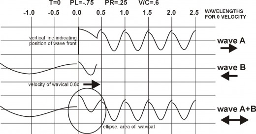
The computer program WAVICAL
100 REM Wavical
110 PI=3.14159:E=2,71828
120 SCREEN 1,0:CLS:KEY OFF: COLOR O,1
130 DIM PL(200),PR(200):REM peak points in space
140 DIM TL(200) , TR(200) : REM time peak point occurred
150 INPUT "enter v/c”;V
160 CLS: rem clears the screen
170 B=(1 - (V^2))^. 5: REM relativity -factor
180 AM=11.5: REM amplitude greater than oscillation
190 EQ=16: REM the elementary charge x 1020
210 WL=60/B:HW=WL/2:REM particle wavelength and half wavelength
240 ADL=(HW)*(1-V):REM time for signal to travel from pr to left peak
250 ADR=(HW) * (1+V):REM time -for signal to travel from pl to right, peak
260 AD=ADL+ADR:REM time between peaks at point pr or point pl
270 ADZ=ADR-ADL
280 PD=AD*V: REM distance signal traveled between peaks
290 SPL=100-5*PD : REM start position for left peak point
300 TL(l)=0:TR(l)=HW*(1+V):REM history of times of peaks
310 TL(2)=TL(1)+AD : TR(2)=TR(1)+AD
320 TL(3)=TL(2)+AD:TR(3)=TR(2)+AD
330 TL(4)=TL(3)+AD:TR(4)-TR(3)+AD
340 TL(5)=TL(4)+AD:TR(5)=TR(4)+AD
350 PL(l)=SPL:PR(l)=SPL+HW*(l+V) : REM history of positions of peaks
360 PL( 2)=PL(1)+PD : PR(2)=PR(1)+PD
370 PL(3)=PL(2)+PD: PR( 3)=PR(2) +PD
380 PL(4)=PL(3)+PD : PR(4)=PR(3)+PD
390 PL(5)=PL(4)+PD:PR(5)=PR(4)+PD
400 ZL=5:ZR=5:Z1=5:Z2=5:ZP=5:REM counters
410 SP=6/(((l-V)^.5) *((1+V)^.5)) : REM factor for time increment
420 H=(TR(ZR) + (HW* (1-V) ) ) : REM time of left peak plus time for signal to j travel from PR to PL
430 FOR T=H TO 4*H STEP SP : REM time increments between images
440 ZL=Zl : ZR=Z2
450 IF TL(ZL) >TR<ZR) AND T<TL (ZL)+ADR) AND (T+SP) >TL(ZL) +ADR) THEN T=TL(ZL)+ADR
460 IF TL (ZL)>TR(ZR) AND T<(TR (ZR)+ADL) AND (T+SP)>TR (ZR) +ADL) THEN T=TR<ZR)+ADL
470 IF ZR>ZL THEN ZP=ZR ELSE ZP=ZL:REM prevents sp counter from becoming zero
480 XL=T-TL(ZL) : REM time since last peak for left peak point
490 KLL=T-TL(ZL):KRR=T-TR(ZR):REM times since last' peaks
500 IF TL(ZL)>TR(ZR) THEN MP=PL(ZL)+KLL : REM Condition to draw impulse line in BB
510 IF TL(ZL)<TR(ZR) THEN MP=PR(ZR)-KRR:REM Condition to draw impulse line in AA
520 GOSUB 810 : REM draws grid bkgd
530 FOR J=0 TO 300 STEP SP/6
540 IF J<MP AND (J+SP/6)>MP THEN J=MP
550 FOR N=(ZP-5) TO (ZP)
560 KL=T-TL(N):KR=T-TR(N):REM time since n peaks
570 LP=PL(ZL)+V*KLL:REM position of moving peak point PL
580 REM IF PL(N)=0 THEN LP=PL(Z1-1)+V*KL
590 RP=PR(ZR)+V*KRR : REM position of moving peak point PR
600 IF PL(N)<>0 AND J=>LP-.l AND J=<RP+. 1 THEN GOSUB 1270 : REM right of PL
610 IF PR(N)<>0 AND J=>LP-.1 AND J=<RP+.1 THEN GOSUB 1360 : REM left of PR
620 IF PR(N)<>0 AND J=<PR(N)+T-TR(N) AND J>RP THEN GOSUB 1110 : REM right of PR
630 IF PL(N) <>0 AND J = >PL(N) -T+TL(N) AND J<L.P THEN GOSUB 1190 : REM left, of PL
640 NEXT N
650 TTA=AA+BB : REM amplitude of combined waves
660 IF TTA>EQ AND AA>AM AND AAS<.001 AND BBS<.001 AND J=MP THEN GOSUB 1030 : REM
exceeds elementary charge at PL
670 IF TTA>EQ AND BB>AM AND AAS<.001 AND BBS<.001 AND J=MP THEN GOSUB 1070:REM
exceeds elementary charge at PR
680 IF TTA>EQ AND AAS<.001 AND BBS<.001 AND J=MP THEN SOUND RND*1000+37,2:REM sounds if EQ exceeded
690 PSET(J,-AA+50) : REM AA curve
700 PSET(J,-BB+80) : REM BB curve
710 PSET(J,-TTA+130) : REM electric field curve
720 IF J=MP AND TL(ZL) >TR( ZR) THEN LINE (J, 65) - (J,95) : REM impulse line moving right in wavical
730 IF J=MP AND TL( ZL)<TR(ZR) THEN LINE (J, 35) - (J,65) : REM impulse line moving left in wavical
740 REM IF J=MP THEN PRINT "mp = " ; (MP-100)/60? "aas=" ; AAS; "bbs="BBS; "tta=" ; TTA; "aa=”;AA: “bb="BB;”sr =";SR/60;"sl=="SL/60;”sp=-“;SP : REM test used to check program
750 AA=0 : BB=0 : CC=0 : DD=0 :TTC=0 : TTA=0
760 NEXT J
770 INPUT UUU:REM to hold image on screen till enter is pressed
780 CLS
790 NEXT T
800 END
810 REM Draws bkgd grid
820 PRINT "T="; (T-(TL(5)+AD) )/60; ''PL="; (PL(ZL)-PL (5) -ADZ )/60;"PR=”; (PR ( ZR) -PL(5)-ADZ)/60 ; "V/C=";V:REM prints legend
830 PRINT" -1.0 -.5 0 .5 1.0 1.5 2.0 2.5 3.00" : REM prints distances
840 X=PL(ZL)+(15*B)+(XL*V) :REM center of particle
850 R=B*30 : REM minor axis length
860 FOR S=-R TO +R STEP B
870 YA=(650-((650*(S^2) )/(R^2)))^.5 : REM equation for ellipse representing particle position
880 PSET(S+X,YA+130) : REM draws top of ellipse
890 PSET(S+X,-YA+130) : REM draws bottom of ellipse
900 NEXT S
905 rem draws vertical lines
910 FOR L=40 TO 300 STEP 30
920 LINE (L s 2O) - (L, 160),2
930 NEXT L
935 rem draws horizontal lines
940 LI NE (0, 35) - (300, 35),2
950 LINE (0,50)-(300,50), 2
960 LINE (0, 65) - (300, 65) , 2
970 LINE (0,80)-(300,80),2
980 LI NE (0, 95)-(300, 95) , 2
990 LINE (0,110)-(300,110),2
1000 LI NE (0,130)-(300,130),2
1010 LINE (0, 150)-(300,150) ,2
1020 RETURN
1030 REM where wave peaks (PL)
1040 Z1=Z1+l
1050 PL(Z 1) = J : TL (Z 1) =T
1060 RETURN
1070 REM where wave peaks (PR)
1080 Z2=Z2+1
1090 PR(Z2)=J:TR(Z2)=T
1100 RETURN
1110 REM waves moving to right of PR
1120 WWR=WL*(1-V) : REM Leading Doppler wavelength
1130 MR=ABS(J-PR(N)) : REM distance to PR
1140 SR=ABS(KR-J+PR(N)) : REM SR=(x+ct) and distance to impulse
1150 HV=(1+.0001*MR)^2 : REM impulse wave spread factor FOR vibration
1160 DA=(E/1.6)^(-0.8*SR/WL) : REM damping factor
1170 AA=(EQ/HV)*DA*COS(2*P1*(SR/WWR)) : REM electric field curve equation
1180 RETURN
1190 REM waves moving to left of PL
1200 WWL=WL* (1+V) : REM trailing Doppler wavelength
1210 ML=ABS(PL(N)-J) : REM distance to PL
I220 SL=ABS(PL(N) - J -KL) :REM SL= (x -ct)
1230 HV=( 1+.0001*ML)^2 : REM impulses wave spread factor for vibration
1240 DA=E^(-0.8*SL/WL) : REM damping factor
1250 BB=(EQ/HV)*DA*COS(2*PI*(SL/WWL)) : REM electric field curve equation
1260 RETURN
1270 REM waves moving to right of PL
1280 WWL=WL*(1-V) : REM leading Doppler wavelength
1290 ML=ABS(J-PL(ZL) : REM distance to PL
1300 SL=ABS(PL(ZL)-J+KLL) : REM SL=(x+ct) and distance to impulse
1310 HV=(1+.0001*ML)^2 : REM impulse wave spread factor for vibration
1320 DA=E^(-0.8*SL/WWL) : REM damping factor
1330 BB=(EQ/HV)*DA*COS(2*PI*(SL/WWL)) : REM electric field curve equation
1340 BBS=ABS((HA/HV)*DA*S1N(2*PI*(SL/WWL)) : REM electric field curve derivative
1350 RETURN
1360 REM waves moving to left of PR
1370 WWR=WL*(1+V) : REM trailing Doppler wavelength
1380 MR=ABS(J-PR(ZR)) : REM distance to PR
1390 SR=ABS(PR(ZR)-J-KRR) : REM SR=(x-ct) and distance to impulse
1400 HV= (1+.0001*MR)^2 : REM impulse wave spread factor for vibration
1410 DA=E^(-0.8*SR/WWR) : REM damping factor
1420 AA=(EQ/HV)*DA*COS(2*PI*(SR/WWR)) : REM electric field curve equation
1430 AAS=ABS((EQ/HV)*DA*SIN(2*PI*(SR/WWR))) : REM electric field curve derivative
1440 RETURN
Computer program ELEORBIT illustrates the Pauli Exclusion Principle
The purpose of this program is to determine the wave pattern in the electron orbit, created by the electron as it rotates around the nucleus of an atom. First divided the lowest energy circular orbit into 2880 points. In figure A-2 each point is represented by the angle A in polar coordinates (R,A), where R is the radius of the orbit, 52.89945 picometers (10-12m). For our unit of length we will use the picometer. Our time unit is about 1/3 x 10-20 second. The velocity of light equals 1 space unit/time unit (1x10-12/0.333333x10-20 = 3x10⁸).
Start with the assumption that the electron consist of two peak points that are constantly emitting electric signals into space. The signal leaving either peak point is traveling with the velocity of light, hence, it will take 2R time units to arrive at the opposite side of the orbit. Since this is the longest distance that the signal will have to travel before encountering a point on the orbit, 2R is the instant chosen to determine the phase at each point on the electron orbit. Therefore the distance traveled by the peak point from 0O to the point where the signal is emitted (R,B), plus the distance that the signal must travel from the peak point (R,B) to a chosen point (R,A) on the orbit, must equal 2R. The phase at the point on the orbit will be the same phase as the peak point at the time the signal left the peak point, and this phase would depend on the time, hence the distance the peak point had traveled before the signal was emitted.
The distance that this peak point travels in polar coordinates is q = B = s/R = vt1/R. From the distance formula in polar form d = (r12 + r22 - 2r1r2cos(q1 - q2))1/2 we get the distance D = R (2 - 2cos(A-B))1/2, where A is the angle from 0O to the selected point (R,A) on the orbit, B is the angle from 0O to where the peak point emits the signal (R,B) and R is the radius of the orbit. The time for the signal to travel from point of origin (R,B) the distance D to the point (R,A) on the orbit is t2 = D/c = R(2 - 2cos(A-B)) 1/2/c. The time for the peak point to travel from (R,0O) to the point of signal origin (R,B) is t1= BR/v, where v is the velocity of the electron around the atom.V = c/137 = 0.00730065c and t1 + t2 = 2R. Therefore
BR/v + R (2 - 2cos(A-B)) 1/2 = 2R or since we can cancel R then B/v + (2 - 2cos(A-B))1/2 = 2.
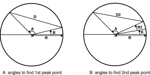
The second peak point is handled the same way, however, it starts at point (R,K) instead of (R,0O). Since the second point is ½ wavelength ahead of the 1st peak point (1.21321 pico- meters) forming an angle of 0.02293426 radians. However using this figure for K then t1 + t2 does not exactly equal 2. Therefore by trail and error we find the value of K to be 0.02292539. The relationship between the angles is
B2/v + (2 - 2cos(A-K-B2)) 1/2 = 2
In the program ELEORBIT, I was unable to calculate directly angles B and B2 for each angle A, therefore, I used a trial and error method to determine the 2880 B angles and the 2880 B2 angles. Since this method is so time consuming, I did the B and B2 calculations in a module that creates a file that can be easily accessed later to run programs.
This program is written so that the images are in 3D, that is by rotating the images about any of the 3 axis (x,y,z) the images can be viewed from any angle. Without any rotation the orbit will appear as a circle and none of the waves would be apparent. When the program, ask you to input the rotation around each axis I suggest for best viewing rotate 90 O around the z-axis, no rotation around the y-axis and 75O or 80 O around the x-axis.
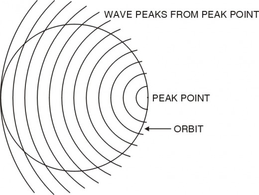
The program will draw 3 views in 3 different situations. One showing the waves produced by the 1st peak point, the 2nd peak point, and the resulting wave from combining the first two, of a single electron in the orbit. Another showing the waves produced by the 1st peak point, the 2nd peak point, and the resulting wave from combining the other two, of a second electron. Still another showing the resulting waves produced by the 1st electron, the 2nd electron, and the resulting wave from combining the two electron waves. At each position the orbit is drawn as a reference for the equilibrium position. These are shown in fig. 15 of this article, illustrating why only two electrons could occupy the same orbit. Notice that on the opposite side of the orbit from the electron, the wavelengths become much longer. This is caused by the way the expanding waves from the peak points intersect with the orbit. The drawing fig. A-3 below illustrates this.
Before starting, type files and enter, all the files will appear. Check to see if the file WAVE already exist.
To load this program press F3, and type eleorbit. To run this program press F2 for run. Four choices will appear. If the file WAVE does not already exist type 12 to create the file WAVE. If the file WAVE already exist or after the file WAVE has been created, type 0 to run program. Since this program is in 3D you must choose what angles to view the drawings. For the best view it is suggested 90O on the z-axis, 0O on the y-axis, and 75O on the x-axis. Next appears 3 choices of 3 different sets of curves.
The computer program ELEORBIT
100 CLS:REM ELEORBIT
110 DIM A(36005, B(36OO),E2<3600)
120 CLEAR 3000
130 DIM A(2380),B<2880),B2(2880)
140 REM Control module
150 PRINT:PRINT" 0 to run program
160 PRINT:PRINT" 12 to create file, WAVE
170 PRINT : PRINT" 3 to print, complete file
180 PRINT : PRINT" 7 to check file
190 PRINT: INPUT"choose number";QQ
200 IF QQ=0 THEN 710
210 IF QQ=12 THEN 330
220 IF QQ=3 THEN 260
230 IF QQ=7 THEN 1820
240 CLOSE
250 END
260 CLS:REM Print complete file
270 OPEN "I”,1, "wave"
280 INPUT #1,N,A(N) ,B(N),B2(N),D,D2
290 IF EOF(l) THEN 320
300 PRINT N; A (N); B (N); B2(N); D; D2
310 GOTO 280
320 GOTO 240
330 CLS :REM Start new file
340 OPEN "0”1,"wave"
350 GOSUB 370
360 GOTO 240
37O CLS:REM Input module
380 K=2.292539E-02:REM starting angle for 2nd peak point
390 PI-3.14159 : E=2. 71828: REM math constant.s
400 R=52.89945#:W=2, 426374#: REM Electron orbit radius and electron wavelength
410 V=7.300065E-03: REM Velocity of electron around atom
420 F=R/W: REM frequency
430 JA=3: REM AMPLITUDE FACTOR
440 FOR A=0 TO 2*PI STEP PI/1440
450 N=N+1
460 A(N)=A
470 FOR B=0 TO 2*V STEEP 2*V/1500
480 IF A=0 THEN B=.014494328#
490 IF N=2 THEM B=,0145101
500 IF N=3 THEN B=.014526
510 IF N~4 THEN B=.014542
520 IF N=5 THEN B=.014558
530 IF N=6 THEN B=.0145736
540 IF N=7 THEN B=.0145897
550 D=(B/V) + ((2 - 2*COS(ABS(A--B) ) ) ^.5)
560 IF D=>1.999 AND D=<2,005 THEN GOTO 580
570 NEXT B
580 B(N)=B
590 ADE=0
600 FOR B2=0 TO 2*V STEP 2*V/1500
610 D2=(B2/V)+((2-2*COS(ABS(A-B2-K)))^,5)
620 ON ERROR GOTO 1810
630 IF D2=>1.999 AMD D2=<2,OO5 THEN GOTO 650
640 NEXT B2
650 B2(N)=B2
660 PR I NT # 1, N , A (N) , B ( N) , B2 (N) , D , D2
670 PRINT N;A(N);B(N);B2(N);D;D2
680 IF N=2880 THEN 700
690 NEXT A
700 RETURN
710 CLS: REM Run program
720 INPUT "ROTATION ABOUT Z AXIS IN DEGREES (90)";A1
730 INPUT "ROTATION ABOUT Y AXIS IN DEGREES (0)"; A2
740 INPUT "ROTATION ABOUT X AXIS IN DEGREES (75)"; A3
750 A 1 =A1/57.29577951#
760 A2=A2/57.29577951#
770 IF B2>.014495 THEN 650
780 A3=A3/57.29577951#
790 PRINT: PRINT" 1 Waves from both peak points on 1st electron & resulting wave
800 PRINT:PRINT" 2 Waves from both peak points on 2st electron & resulting wave
810 PRINT:PRINT" 3 Resulting waves from both electrons & resulting wave from both
820 PRINT:INPUT "Enter number";QQ
830 S=2: REM scaling factor
840 K=2.292539E-02: REM Starting angle for 2nd peak point
850 PI=3.14159!E=2.71828:REM Math constants
860 R=52.89945#:W=2.4263748:REM Electron orbit radius and electron wavelength
870 V=7.300065E-03:REM Velocity of electron around atom
880 F=R/W: REM frequency
890 JA=3:REM Amplitude Factor
900 OPEN "I”,1, "WAVE"
910 INPUT #1, N, A(N), B(N), B2(N), D, D2
920 IF EOF (1) THEN 940
930 GOTO 910
940 SCREEN 1,0: CLS:KEY OFF:COLOR 0,1
950 CIRCLE (150, 40) , 1: CIRCLE ( 150, 100) , 1 : CIRCLE (150, 160) , 1 : REM represents nucleus
960 IF QQ=1 THEN 990
970 IF QQ=2 THEM 1190
980 IF SQ=3 THEN 1410
990 REM Waves from both peak points on 1st electron & resulting wave
1000 FOR N=0 TO 2880
1010 X=R*COS (A (N) ) : Y= R*SIN ( A (N ) ) : Z= 0: GOSUB 1720
1020 PSET(XB+150,YB+40),2
1030 PSET(XB+150,YB+100),2
1040 PSET (XB+150,YB+160) ,2
1050 T1=B(N)/V:REM Time 1st peak point has traveled before signal emitted
1060 X= R*COS ( A (N)) : Y=R*S I N (A (N) )
1070 Z1=JA*SIN (2*PI*F*T1) : Z---Z1
1080 GOSUB 1720
1090 PSET(XB+150,YB+40)
1100 T2=(B2(N)+K)/V:REM Time 2nd peak point has traveled till signal emitted
1110 Z2=JA*SIN(2*PI*F*T2): Z=Z2
1120 GOSUB 1720
1130 PSET ( XB+150, YB + 100 )
1140 Z=Z1+Z2
1150 GOSUB 1720
1160 PSET(XB+150,YB+160)
1170 NEXT N
1180 GOTO 240
1190 REM Waves from both peak points on 2nd electron & resulting wave
1200 FOR N=0 TO 2880
1210 X=R*COS(A(N)): Y=R*SIN(A(N)):Z=0: GOSUB 1720
1220 PSET ( XB + 150, YB + 40) , 2
1230 PSET ( XB + 150, YB + 100) ,
1360 Z=Z1+Z2
1370 GOSUB 1720
1380 PSET (XB+ 150, YB+160)
1390 NEXT N
1400 GOTO 240
1410 REM Waves from both electrons & resulting wave
1420 FOR TP = 0 TO W STEP W / 8
1430 FOR N=0 TO 2880
1440 X - R*COS (A (N) ) : Y=R*SIN (A (N) ) : Z= 0: GOSUB 1720
1450 PSET (XB+150., YB+40) ,2
1460 PSET (XB+150., YB+100) ,2
1470 PSET (XB+150., YB+160) ,2
1480 T1=B(N)/V
1490 X=R*COS(A(N)):Y=R*SIN(A(N))
1500 Z1=JA*-SIN(2*PI*F*(T1+TP))
1510 T2=<B2(N)+K)/V
1520 Z2=JA*SIN(2*PI*F*(T2+TP))
1530 Z1+ Z2
1540 GOSUB 1720
1550 PSET (XB+150., YB+40)
1560 IF N<1440 THEN QD= 1440
1570 IF N=>1440 THEN QD= -1440
1580 T1=B(N+QD)/V
1590 Z4=JA*-SIN(2*PI*F* (-T1 - TP) )
1600 T2 = (B2 (N+QD) + K) / V
1610 Z5=JA*-SIN(2*PI*F*(-T2-TP))
1620 Z=Z4+Z5
1630 GOSUB 1720
1640 PSET(XB+150,YB+100)
1650 Z=Z1+Z2+Z4+Z5
1660 GOSUB 1720
1640 PSET(XB+150,YB+160)
1680 NEXT N
1690 PRINT "Time ="TP "Press enter to continue": INPUT II
1700 CLS:NEXT TP
1710 GOTO 240
1720 REM 3-D MODULE
1730 XA=X*COS (A1) - Y*SIN (A1)
1740 YA=X *SIN ( A1)+Y*COS(A1)
1750 X B=X A * COS(A2) - Z * SIN (A2)
1760 ZA=XA*SIN(A2)+Z*COS(A2)
1770 ZB=ZA*COS(A3)-YA*SIN(A3)
1780 YB=ZA*SIN (A3)+YA*COS(A3)1790 XB=XB*S:YB=YB*S/1.2: ZB=ZB*S
1800 RETURN
1810 RESUME 630:REM ERROR CORRECTION
1820 CLS:REH CHECK FILE
1830 OPEN “I”,1,”WAVE
1840 INPUT #1, N, A(N), B(N), B2(N), D, D2
1850 IF EOF (1) THEN 1890
1860 IF D<1.999 OR D>2.O05 THEN PRINT N; A(N); D; D2
1870 IF D2<1,999 OR D2>2.005 THEN PRINT N; A(N); D; D2
1880 GOTO 1840
1890 GOTO 240
The End


